Rack space in the data center has long been at a premium, but emerging technologies and an increasing number of applications and amount of data that demand high-bandwidth, low-latency transmission and highly virtualized environments are driving data center complexity and fiber cabling densities to an all-time high-all of which comes with some unique challenges and the need for innovative design and solutions.
Changing Architecture Means More Infrastructure
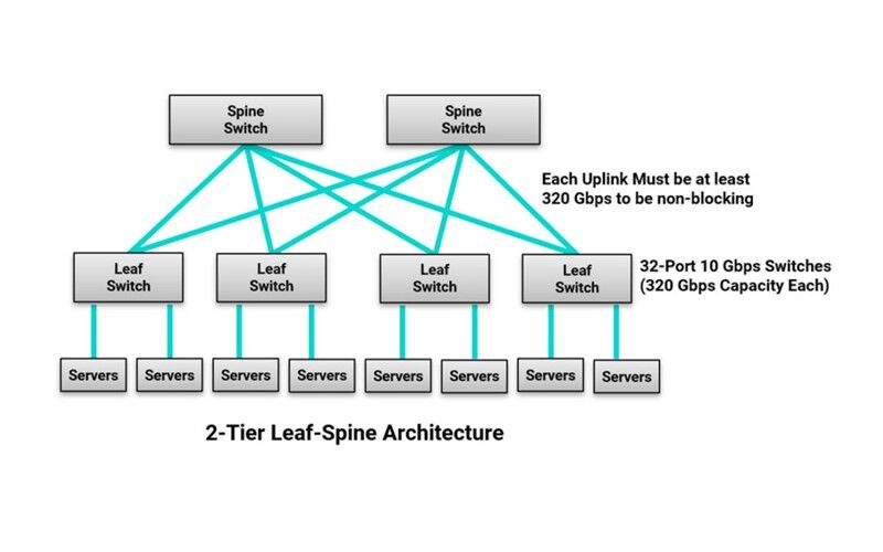
While fiber density is increasing in the data center due to the sheer amount of equipment needed to support emerging applications and increasing data, it is also being driven by server virtualization that makes it possible to move workloads anywhere in the data center. With increasing virtualization comes the rapid migration from traditional three-tier switch architecture with a north-south traffic pattern to leaf-spine switch fabric architecture with just one or two switch tiers and an east-west traffic pattern.

In a leaf-spine architecture, every leaf switch connects to every spine switch so there is never more than one switch between any two leaf switches on the network. This reduces the number of switch hops that traffic must traverse between any two devices on the network, lowering latency and providing a superior level of redundancy. However, it also increases the overall amount of fiber cabling in the data center. In a leaf-spine architecture, the size of the network is also limited by the number of ports available on the spine switches, and to be completely non-blocking, the sum of the bandwidth of all equipment connections on each leaf switch must be less than or equal to the sum of the bandwidth of all of the uplinks to the spine switches.
For example, if a leaf switch has thirty-two 10 Gbps server ports (i.e., 320 Gbps capacity), it will need a single 400 Gbps uplink, two 200 Gbps uplinks, four 100 Gbps uplinks, or eight 40 Gbps uplinks to be completely non-blocking. It’s easy to see how the number of fiber uplink connections is increasing!
Optimizing Port Utilization
To help maximize space, maintain low latency, and optimize cost, the use of link aggregation via break-out fiber assemblies is on the rise. It’s not uncommon to find enterprise customers leveraging a single 40 Gbps switch port on a leaf switch to connect to four 10 Gbps servers. As switch speeds increase, link aggregation will offer even greater port utilization and workload optimization.
In January of 2020, the ratification of IEEE 802.3cm for 400 Gbps operation over multimode fiber includes 400GBASE-SR8 over 8 pairs and 400GBASE-SR4.2 over 4 pairs using two different wavelengths. These applications have broad market potential as they enable cost-effective aggregation with the ability to connect a single 400 Gbps switch port to up to eight 50 Gbps ports. With the introduction of full duplex applications like 50GBASE-SR and short wave division multiplexing that supports 100 Gbps over duplex fiber via the pending IEEE P802.3db, MTP-to-LC hybrid assemblies will be essential.
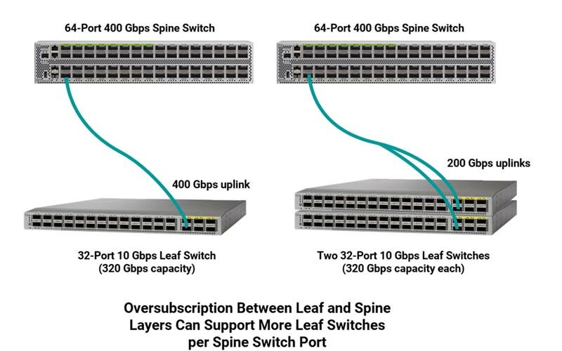
Some data centers also employ link aggregation at the leaf-spine connection to maximize port utilization. For example, rather than using four 100 Gbps ports on a spine switch to connect to a 32-port 10 Gbps leaf switch in a non-blocking architecture, a single 400 Gbps port can be used. However, data center designers strive to carefully balance switch densities and bandwidth needs to prevent risky oversubscription and costly undersubscription of resources at every switch layer.
While oversubscription is not considered completely non-blocking, it is rare that all devices would be transmitting simultaneously so not all ports require maximum bandwidth at the same time. Certain applications can also risk some latency. Oversubscription is therefore commonly used to take advantage of traffic patterns that are shared across multiple devices, allowing data center operators to maximize port density and reduce cost and complexity. Network designers carefully determine their oversubscription ratios based on application, traffic, space, and cost, with most striving for ratios of 3:1 or less between leaf and spine layers.

For example, if we go back to the example of a leaf switch with thirty-two 10 Gbps ports (320 Gbps capacity), instead of undersubscribing by using a 400 Gbps uplink, it may make sense to use a 200 Gbps uplink to the spine switch with an oversubscription ratio of 320:200 (8:5), which is still considered a low oversubscription ratio. This allows a single 400 Gbps port on the spine switch to now support two leaf switches.
While these practices are ideal for switch port utilization, they can make for more complex data center links. That combined with an overall increased amount of fiber means patching areas between leaf and spine switches are denser than ever. In a very large data center, we could be talking about a patching area that encompasses multiple cabinets and thousands of ports for connecting equipment. Think of a meet-me room in a colocation where large cross-connects are used to connect tenant spaces to service providers, or a cloud data center where thousands of switches connect tens of thousands of servers. Not only is that a lot of ports to manage, but it’s also a lot of cable in pathways and cable managers.
Managing It All
In ultra high-density fiber patching environments, accessing individual ports to reconfigure connections can be very difficult, and getting your fingers into these tight spaces to access latches for connector removal can cause damage to adjacent connections and fibers. This is of particular concern when deploying an interconnect scenario that can require accessing critical connections on the switch itself-the last thing you want to do is damage an expensive switch port while trying to make a simple connection change or inadvertently disconnect the wrong or adjacent connection(s). At the same time, the implementation of various aggregation schemes and links running at higher speeds means that downtime could impact more servers. That makes it more critical than ever to maintain proper end-to-end polarity that ensures transmit signals at one end of a channel match receivers at the other end.
Thankfully, cabling solutions have advanced to ease cable management and polarity changes in the data center. For parallel optic applications in switch-to-switch links like 8-fiber 200 and 400 Gbps, Siemon uses a smaller RazorCore™ 2mm cable diameter on 12- and 8-fiber MTP fiber jumpers. To save pathway space between functional areas of the data center, Siemon also uses smaller-diameter RazorCore cabling on MTP trunks. Siemon multimode and singlemode MTP jumpers, trunk assemblies and hybrid MTP-to-LC assemblies also feature the MTP Pro connector that offers the ability to change polarity and gender in the field. (read more about the MTP Pro and polarity.)

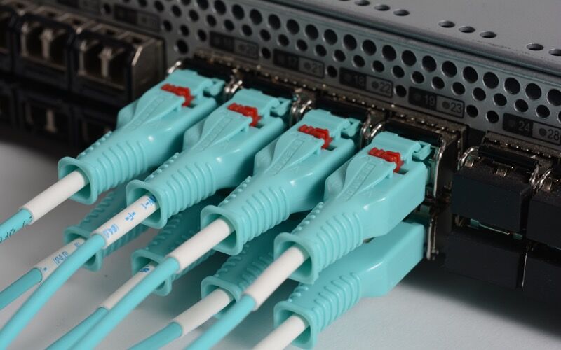
For duplex connections, Siemon’s LC BladePatch® jumpers and assemblies offer a smaller-diameter uni-tube cable design to reduce pathway congestion and simplify cable management in high-density patching environments. Available in multimode and singlemode, the small-footprint LC BladePatch offers a patented push-pull boot design that eases installation and removal access, eliminating the need to access a latch and avoiding any disruption or damage to adjacent connectors. LC BladePatch also features easy polarity reversal in the field.
In fact, Siemon recently enhanced the LC BladePatch with a new one-piece UniClick™ boot that further reduces the overall footprint to better accommodate high-density environments and makes polarity reversal even faster and easier. With UniClick, polarity reversal involves just a simple click to unlock the boot and rotate the latch with no loose parts and without rotating the connector and fiber, eliminating the potential for any damage during the process. Innovative push-pull activated LC BladePatch duplex connectors are also available on MTP to LC BladePatch assemblies to easily accommodate breakouts for trending link aggregation.


